The Handbook
1. Handbook
(handbook How Ornithopters Fly
is only in German)
How does an ornithopter create thrust and lift - despite of alternating flapping directions? The answer can be found in the handbook based on well-known results of research. Apart from the aerodynamics of up- and downstroke, the dynamics of the flapping wing is also taken into consideration. The correlations are described with equations and diagrams. Your own calculations are made possible, which may be helpful for developing specific ornithopter models. Furthermore, you will find useful tips for ornithopter models in practice.
The relatively simple equations for changing circulation distributions make it possible to vary the lift distribution and to determine the appropriate wing twisting.
-
- Vortex system behind an ornithopter
under quasi-stationary flow conditions
The ornithopter subject also extends to the field of bionics. It is an attempt to develop better ornithopters by understanding the biological design principles of birds.
You can download the handbook (in German) and photos.
- PDF 3.3 MB
- PDF 5.9 MB
- PDF 9.2 MB
The handbook was translated in French by Jean-Louis Solignac. With his knowledge as an aerodynamics expert and with his experience he has contributed a lot to the improvement of the handbook.
Jean-Louis Solignac, Maître de Recherche,
acted as deputy head of the department Principles of Aerodynamics
in the
directorate of aerodynamics of the national French research institute O.N.E.R.A.
(Office National d'Études et de Recherches Aérospatiales). You can
find his translation of the handbook here on the French
site.
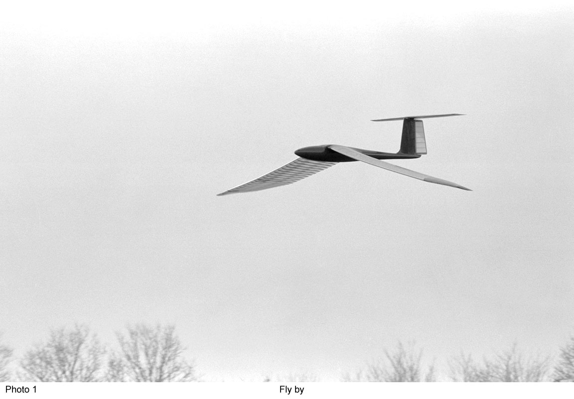
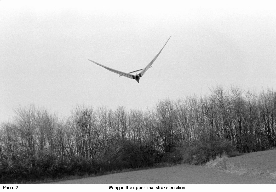
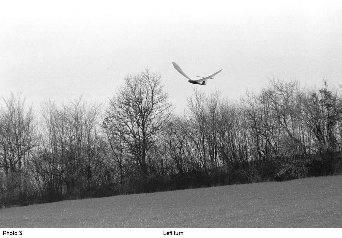
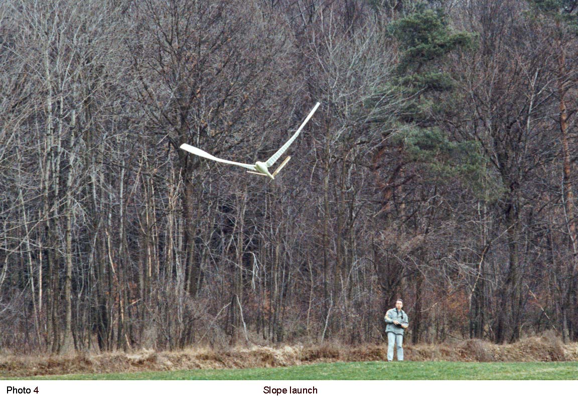
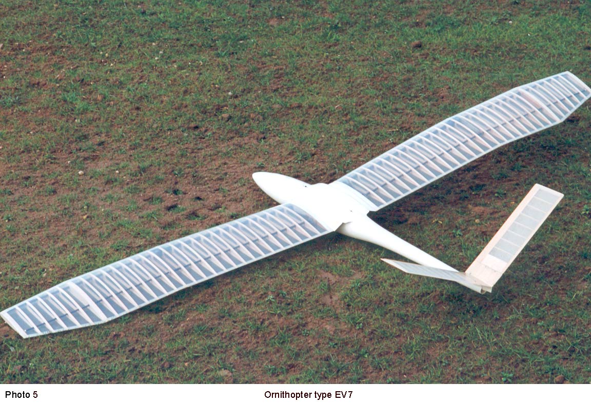
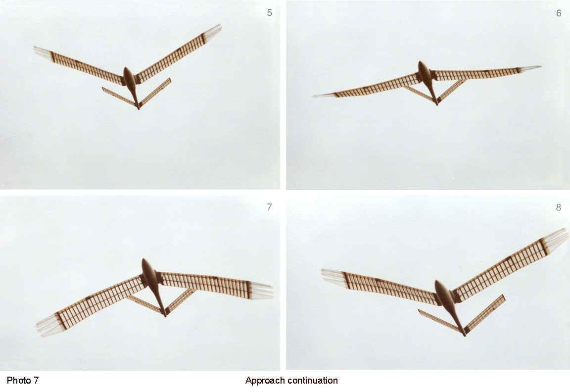
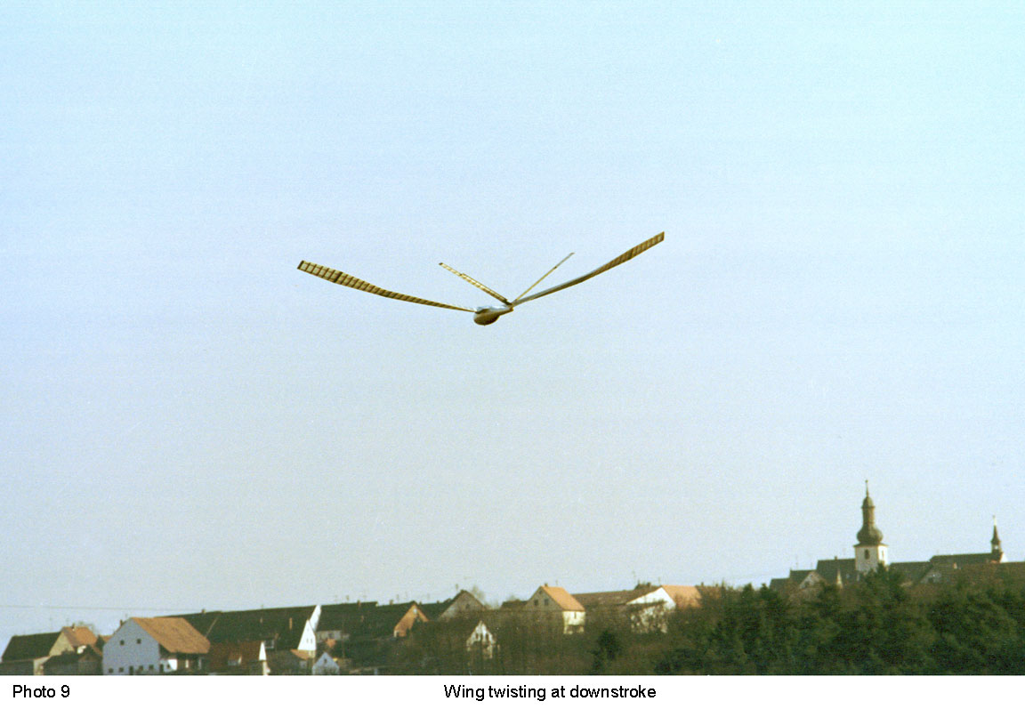
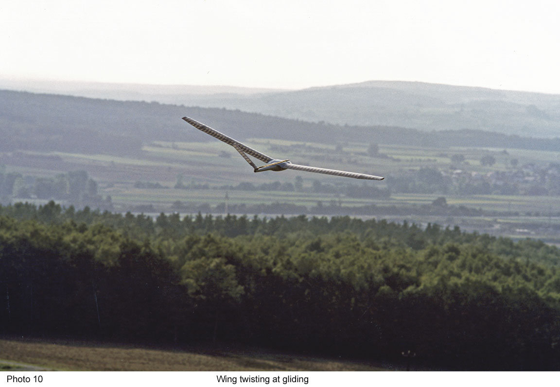
The photos of the handbook


2. Calculation of flapping wings
under the precondition of quasi-stationary
conditions
The equations presented in the handbook are used in several calculating tools. Thereby underlies the following method of calculation.
First, the flapping wing is theoretically divided into stripes with a very small span. Then, for each of these wing sections the aerodynamic forces are calculated under stationary or constant oncoming airflow conditions. Their sum results from a numerical integration over the whole wing span.
-
- Configuration of the forces

In this way, you get the total forces of lift and propulsion of the flapping wing at a fixed moment of time of the stroke cycle. The corresponding wing twisting, the profile- and induced drag can be determined in the course of this calculating scheme, too.
-
- Locations for calculation
This process is repeated in equal time segments of the wing stroke motion. Thereby, the changed factors as for instance the distribution of circulation, conditions of oncoming airflow or the dihedral of the wing form the basis. At the same time, stationary conditions are postulated. It is therefore presumed that the airflow does not change during the time span of calculating. Furthermore, unsteady airflow behaviour is not considered.
That way - thus by stringing together different steady conditions - time force progression under quasi-steady conditions results.
The force of a whole stroke motion can be obtained by numeric integration of the force progression over the considered time span. Thereby, up- and downstroke of the wing are advisably considered separately. Finally, the summary of up- and downstroke forces leads to the total forces of a whole stroke cycle.
-
- Frequency of wing beats and the weight of birds
by
 Heinrich Hertel
But according to ![]() Erich von Holst this quasi-steady method> only
leads to useful results during a fast forward flight with relatively low flapping
frequencies (large birds). Otherwise, the influences of unsteady airstream behaviours
become too strong. Later publications verify these constraints. As an example,
also the following analysis by M. Neef.
Erich von Holst this quasi-steady method> only
leads to useful results during a fast forward flight with relatively low flapping
frequencies (large birds). Otherwise, the influences of unsteady airstream behaviours
become too strong. Later publications verify these constraints. As an example,
also the following analysis by M. Neef.
-

- Revised principle arrangement of forces on the flapping wing
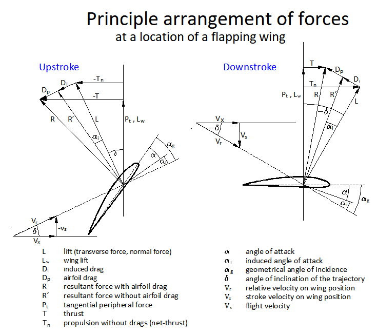
In the manual I tried to describe the physical parameters of a flapping wing for a calculation model. In the Arrangement of forces at flapping wing (in German, PDF 0.5 MB) some of them have been redefined.
3. Result of the latest research
Dr.-Ing. Matthias F. Neef has examined in his dissertation Analysis of the flapping
flight by numeric flow design engineering
the unsteady flow at a moved wing.
Thereby, he reached a similar vorticity system as aforesaid. However, his picture
with a sinusoidal flapping motion-sequence is more specified and more detailed,
but under transient flow conditions.
-
- Isolines of the circulation along the flight path
under transient flow conditions
The dissertation includes a general view about flapping flight and more exciting pictures (please look at related link 1. and 2.).
4. The tip vortex of the flapping wing
The isolines of circulation
of a flapping wing shown above also can be visualized
as single vortex filaments. Vortex filaments running parallel and with a same
direction of circulation, twist themselves to a single vortex in their shared
centre at the wake of the wing. In this way, most of the vortex filaments on one
wing side together form one wing tip vortex.
-
- Wing tip vortices of the flapping wing

The vortex wake behind the flapping wing shows lateral contraction in regular
intervals when viewed from above (please look at external link 3).
During a flapping period, the starting point of the tip vortex obviously moves
bidirectionally at the trailing edge of the flapping wing, during upstroke in
the direction of the wing root and during downstroke in the direction of the wing
tip. According to Jeremy Rayner, the motion is between the wrist and the wing
tip. Approach vortices are not visible (please look at J. Rayner, Vertebrate
flapping flight mechanics and aerodynamics and the Evolution of flight in bats
in ![]() Nachtigall W. 1986, BIONA-report 5).
Nachtigall W. 1986, BIONA-report 5).
The lateral movement of the vortex attachment points at the trailing edge of the wing has also been observed in birds (please look at related link 3, Fig. 1 and at the describing of the Basic gaits).
-

- Helical wing tip vortices or
thrust jets
(blast of air) of a bird in continuous-vortex gait during cruise flight or in distance flight.

When we imagine the wing tip vortex in the adjacent picture in three-dimensions be aware a surprising view.
The starting point of the vortex of one wing side not only moves bidirectionally along the trailing edge of the wing. It also follows the flapping motion. Seen in flight direction these both motions together resulted in an approximately circular path line. If now also include the forward motion of the flapping wing one sees the helical shape of the wing tip vortex spreading backwards.
Also the tip vortices of a propeller are arranged in a helical shape (please look
at related link 4). They wrapped the propeller thrust jet
and are an essential part of it. In opposite to the propeller at the flapping
wing simply the windings of the tip vortices are pulled more apart. Hence, in
the three-dimensional view of this vortex picture will be visible a thrust
jet
at each side of the flapping wing.
In order to generate large thrust with an flapping wing, the cross-section of the thrust jet is to make as large as possible. Shifting of the spanwise distribution of lift is a dominant factor here. At downstroke the lift should be shifted as far as possible towards to the wing tip and at upstroke towards to the wing root. Furthermore, the stroke angle of the wing should be chosen relatively large without, however, losing sight of thereby decreasing lift.
-
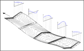
- Reconstruction of the
lift distributions
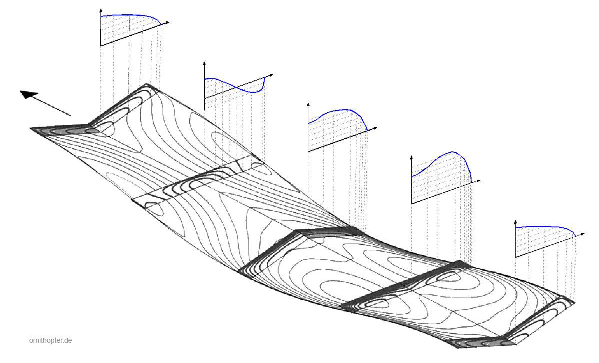
One can derive the lift distributions at the wing from such a vortex image. The position of the vortex filaments at the trailing edge of the flapping wing is used for this purpose. Each vortex filament corresponds to a stage of equal lift size. The closer the vertebral lines are to each other, the greater the change in lift in the concerned wing section. For more information on the procedure, please see Arrangements of wing tip vortices on flapping wings, version 4.2, (PDF 0.5 MB).
In the picture above it is noticeable that the lift distribution in the lower final stroke position is significantly larger than in the upper final stroke position. This is due to the aerodynamic phase shift under non-steady flow conditions. The large lift of the downstroke remains effective over a longer period of time. The same also applies to the upper final stroke position, where the lift is reduced by the previous upstroke. Under stationary flow conditions, the lift distribution of a rectangular wing would be present in both final stroke positions (please look at the dissertation by Dr.-Ing. Matthias F. Neef, e.g. page 204, Fig. 99, related link 1). Thus, the aerodynamic phase shift helps small birds and ornithopters to avoid turning of the wing root near the lower final stroke position, in order to increase lift in this period of time.
-
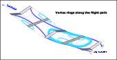
- Vortex rings along the flight path at flapping flight
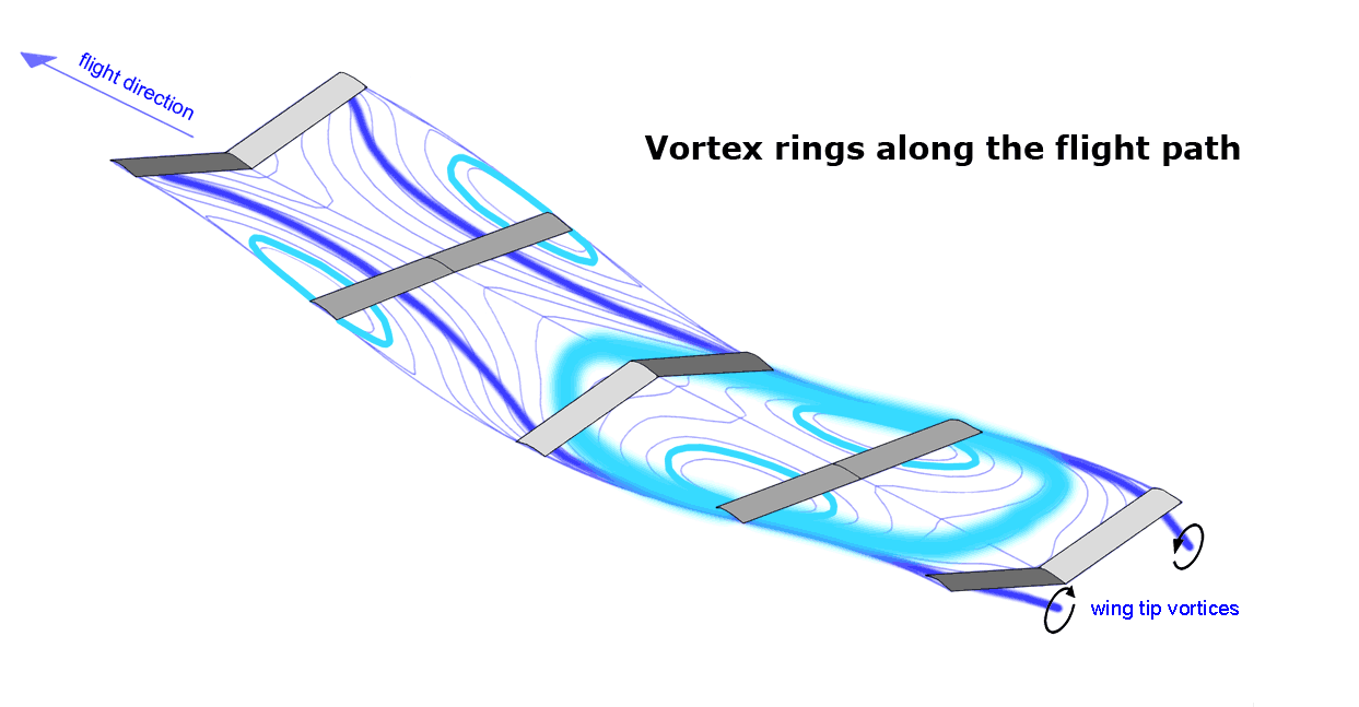
Lift components that are not shifted, but will be built up and down with each wing beat, leaves vortex rings along the flight path. They occur in addition to the wing tip vortices. Especially the starting vortices of the vortex rings increase the induced drag. This is also true for negative lift. In the shown example, the vortex-rings are arranged phase-shifted to the flapping motion.
At upstroke, the source of the vortex rings is clear. Negative lift exists in the hand wing area. It cannot be taken over from the arm wing. Therefore, it has to be generated again on both wing sides with every wing beat. This produces the two vortex rings.
During the downstroke, in principle, the hand wing can take positive lift from the arm wing. In the present case, however, this is not enough for the downstroke (please see above image). Therefore, a part of the lift has to be built up and taken down again with every wing beat. Thereby in particular a large vortex ring is formed here, which encloses the arm and hand wings of both wing sides together. It consists of relatively large numbers of vortex filaments here and is correspondingly strong, stronger than the wing tip vortex. This corresponds in a first approximation to a Ring-vortex gait.
In addition, a small vortex ring is created on each wing side in the hand wing area. It results from the increased lift in this area. Therefore, it is more advantageous to work with approximately constant lift during a flapping period.
-

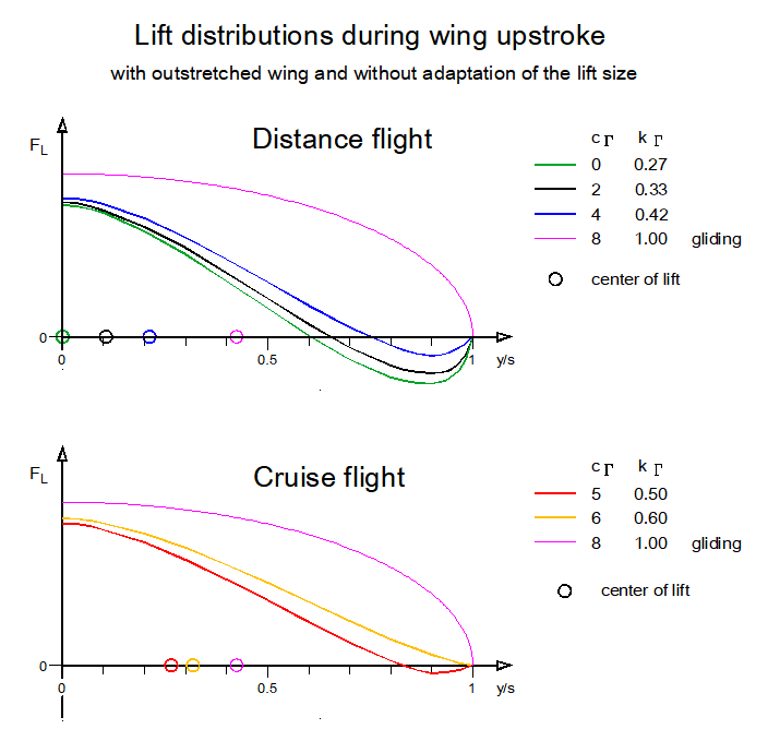
- Induced drag
- at constant circulation and
- at constant angle of incidence at the wing root.
Its size is related to the induced drag of an elliptical lift distribution.

Energy is required for the formation of the vortices.The
size of the associated losses can be described with the help of the induced drag
(F_di). In the design of Distance and cruising flights
it is good to know the tendency of the induced drag. It is determined here using
the calculation method by ![]() R. T. Jones (1950). For its delineation the
induced drag of the elliptical lift distribution (F_di ell) serves as reference
value. As is well known, the induced drag has thereby its minimum in wings with
limited wingspan. If the circulation-characteristic-number c_Γ (c-gamma)
is varied, this results in the adjacent diagram (as in the handbook, Fig. 3.2).
R. T. Jones (1950). For its delineation the
induced drag of the elliptical lift distribution (F_di ell) serves as reference
value. As is well known, the induced drag has thereby its minimum in wings with
limited wingspan. If the circulation-characteristic-number c_Γ (c-gamma)
is varied, this results in the adjacent diagram (as in the handbook, Fig. 3.2).
The circulation factor k_Γ (k-Gamma) also shown is also related to a wing flying with elliptical circulation or lift distribution in gliding flight (k_Γ = 1). The basis is always the model from the handbook.
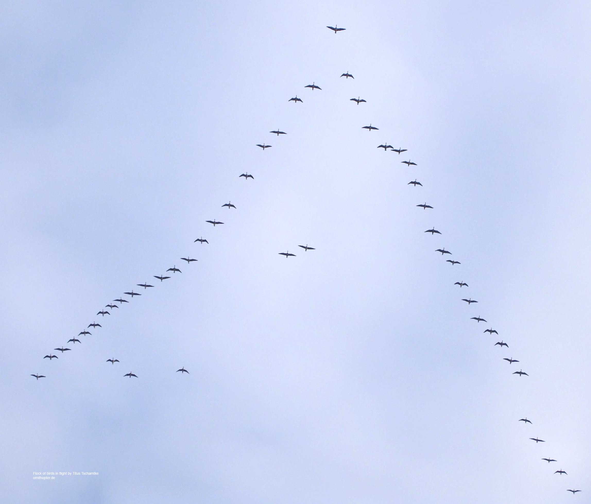
For a flapping flight with smaller upstroke circulation-characteristic-number than
five and with approximately constant lift, therefore, a bending of the hand wing
is very useful (please see Distance flight
in diagram Lift
distributions during wing upstroke from the site gait
change). Its winglet effect reduces the flow along the wing and thus the induced
drag. This increases the efficiency factor of the flapping wing. The point of
attachment of the wingtip vertebra to the trailing edge of the wing s lies always
close to the wrist during upstroke, regardless of whether the hand wing is bent
downward strongly or only slightly (please see also the flight modes distance
flight and cruising flight).
5. Formation flight of birds
-
- Downwash distributions on the wing of an ornithopter
in cruising flight

When a bird joins a V-shaped staggered flight formation, there is a measurable power saving. It arises in particular as a result of aerodynamic changes. Using the flapping wing theory of an ornithopter, it is possible to draw conclusions about the effect of energy saving. Especially waterfowl use the formation flight. However, the energy savings may also be as a result of the transition from distance flight to cruise flight.
In conjunction with the generation of its lift, each bird inevitably generates a wing-tip vortex at each of its two wing tips. For it this implies a loss of energy. This is relatively high, especially for birds with high wing loading and small wing aspect ratio. The following bird now can try to facilitate its own flight work with the energy content of one of these two tip vortices.
-
- Drag reduction at the formation flight of birds

Well known is the hypothesis that the following bird take advantage from the uplift of its bird flying ahead (please look at related link 5, the image on the right and the following image). However, a clear up wind exists only directly at the wing tip of the bird flying ahead. Behind it, its wing tip vortex develops and thus its wake vortex as downwind field. If the following bird flies with a wing tip just in the centre of this tip vortex, so lift exists only in its outer wing area of one wing. In the inner wing area, it has to accept a downwash (please see the following image). Behind the wing the tip vortex is namely an important part of a downwind wake.
However, it seems possible, at least in gliding flight, to use the torque of the tip vortex of the bird flying ahead to reduce the rotation of the own counter-rotating wing tip vortex (please see related link 6). But gliding birds in formation flight you only see very rarely in nature and surely also only for a short time (please see related link 7).
-
- Formation flight with up wind inside the downwash wake of the bird flying
ahead during gliding flight.
Under it is shown the course of the downwash velocity behind the bird flying ahead, based on the surrounding air space.
During flapping flight the wing tip vortex moves always along the trailing edge of the wing in and out.

The benefit of this one-sided up wind is dubiously already in gliding flight. This is even more true also in flapping flight, because with it the distance between the two wing tip vortices changes cyclically, please see the article Arrangements of wing tip vortices on flapping wings (version 4.2, PDF 0.5 MB).
-
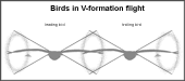
- This is the most probable arrangement of birds and their wing tip vortices
during flight in V-formation.
With tapered wings, the thrust jets are further inwards.
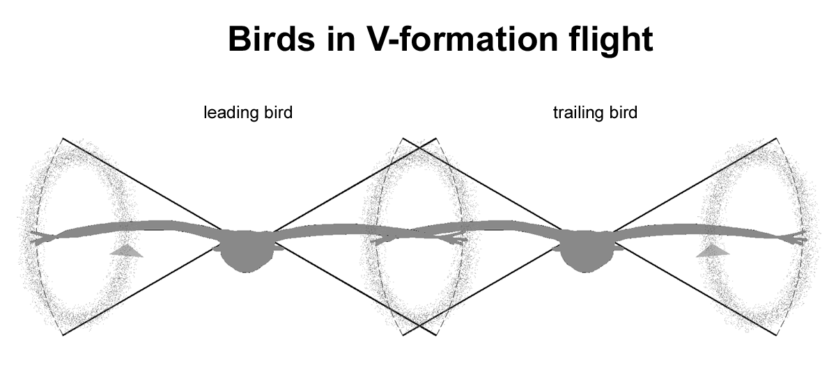
In the paper some theses of formation flight are described and how its benefit might be achieved. The most probable configuration of the bird arrangement is shown here on the right. Similar to two counter-rotating propellers arranged one behind the other, the trailing bird works with a higher efficiency. However, part of the drop in performance when joining the V-formation may also result in a final transition from distance flight to cruise flight.
-
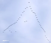
- Flock of birds in flight
Photographer Titus Tscharntke
The problem for the following bird is the optimal adjustment of all distances in the three-dimensional space behind the bird flying ahead. It must try to adjust the distances to the flapping wings of its bird flying ahead in a way that the proper part of the bird flying ahead vortex passes it in a suitable moment and at the optimal position. It can surely feel the best flight position, but thereby it must also make compromises. Anyway, in the theory of formation flight of birds many questions remain open. For more information, please see the Handbook, annexe E, (download above).
6. Related Links
to the
theory of flapping wings
- Matthias Neef,
Analyse des Schlagfluges durch numerische Strömungsberechnung
(2002), e.g. page 204, Fig. 99:
https://publikationsserver.tu-braunschweig.de/receive/dbbs_mods_00001361 - Tatjana Hubel,
Untersuchungen zur instationären Aerodynamik
(2006)
an einem vogelähnlichen Flügelschlagmodell
http://tuprints.ulb.tu-darmstadt.de/800/ - Tyson L. Hedrick, Bret W. Tobalske and Andrew A. Biewener,
Estimates of circulation and gait change based on a three-dimensional kinematic analysis of flight in cockatiels (Nymphicus hollandicus) and ringed turtle-doves (Streptopelia risoria)
please look at Fig. 1. AContinuous-vortex gait
https://jeb.biologists.org/content/205/10/1389.full - Prof. Dr.-Ing. Ingo Rechenberg provides material for his bionic lectures,
for example PowerPoint-Script 4:
Vom Vogelflügel zur Windturbine BERWIAN, Verstehen und Kopieren eines biologischen Prinzips
(for propeller tip vortices, please look at slide 23)
https://www.slideserve.com/halee-atkins/ingo-rechenberg - Malte Andersson and Johan Wallander,
Kin selection and reciprocity in flight formation?
https://academic.oup.com/beheco/article/15/1/158/331110 - NASA - Dryden Flight Research Center,
Autonomous Formation Flight
(2001):
https://www.nasa.gov/centers/dryden/history/pastprojects/AFF/index.html - Anja Soklic,
Energy demand and adaptations of migrating birdsEnergy demand and adaptations of migrating birds
,
cover photo of gliding cranes in formation flight:
https://blogionik.org/blog/2017/12/07/energy-demand-and-adapatation-of-migrating-birds/