Ball screw drive
of the ornithopter model EV8
1. Components

For transforming a rotating motion into a linear motion a ball screw is used
for the EV8. Paul MacCready has used a corresponding
technology for his pterodactyl replica QN
in 1985 (For details about
his drive principle of QN
please look at the ![]() papers, in German).
papers, in German).
For the hereby chosen dimensions a revolution reduction of 38:1 is included - based on one stroke cycle. The efficiency for both conversion directions constitutes of about 0.9. These excellent properties were the crucial factor to renew the drive development. But therefore two motor reversals of rotation are necessary in every stroke cycle. This process corresponds to the change of rotation direction of small servo-driven ornithopters.
Note:
Instead of the ball screw drive a ball reverser actuator may also be used.
Then, the electric motor must not change the rotating direction (please look
at related link 1).
New development
If such a spindle drive to day will be designed by experts it could be very
compact and effective (please look at related link 2).
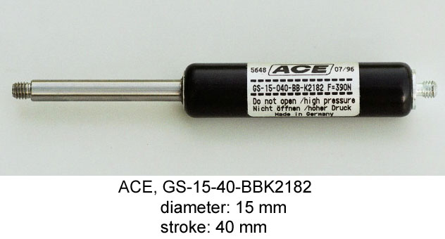
Spring for Lift Compensation
Instead of the inflatable pneumatic spring with a rolling-diaphragm usually
used in the EV-models (Please look at driving
mechanism of the EV4), an industrial gas spring
is used in the EV8. Unfortunately, its spring force
is not repeatedly adjustable to zero (e.g. for the test run of the drive),
but its spring rate is very small.
With great spring forces in connection with a small spring rate gas springs offer advantages to corresponding steel springs. They have a smaller design and lower weight - but also higher losses.
With an effective energy recirculation via the ball screw drive and the speed
control in the battery packs this so-called compensating spring
can
later be omitted.
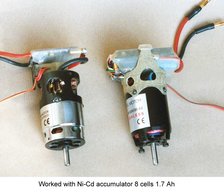
Motor
At the beginning of the EV8 development a brush
less motor was planed - at that time still with sensors - because of its relatively
small mass moment of inertia. But after model completion there was no speed
control with a sufficient short delay at reversal of rotation. Therefore a
motor with carbon brushes had to be used instead. Today, there are also speed
controls for brush less motors with a sufficiently fast reversal of rotation.
The calculated required average wing input power of the EV8 was about 67 Watt. Taking all losses into account, the average motor input power was 127 watts (maximum value of a flapping period 199 Watt).
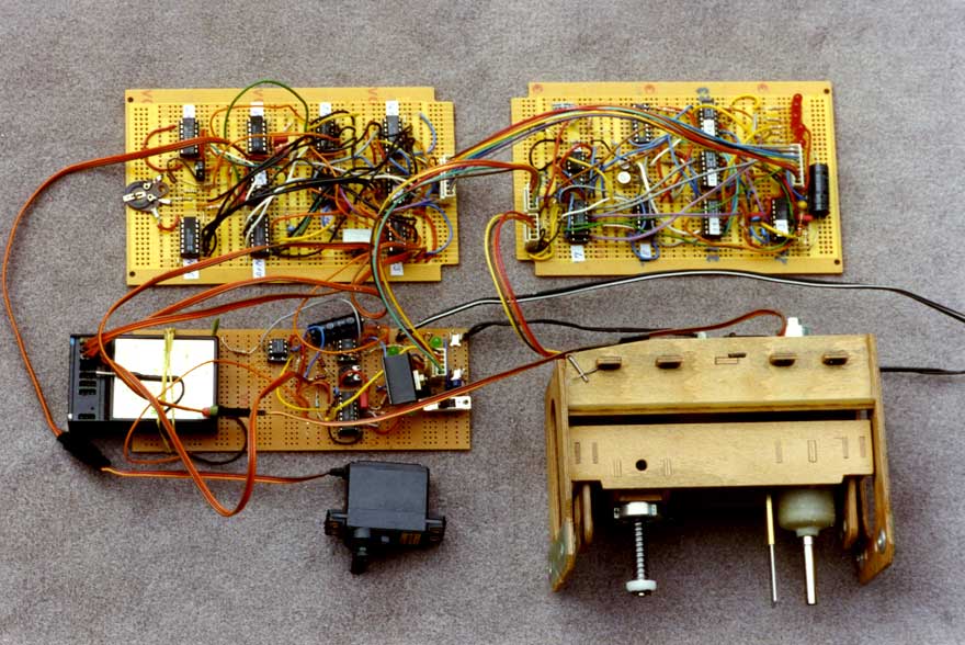
Electronic
In the course of testing the shown test setup the decision was made to accomplish
it with a programmable logical module (also called PLD or microcontroller).
Lacking sufficient programming knowledge I could only substitute about half
of this hardware with it at first.
-

- Download
BASIC program
(zip 8 KB)

But in the meantime microcontrollers have become so capable, that even with a simple BASIC programming language all can be stored in only one chip. With the pictured storage-programmable control device one can control drives for flapping frequencies up to 8 Hz.
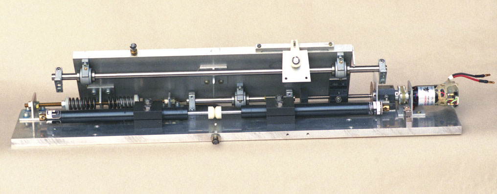
2. Driving mechanism
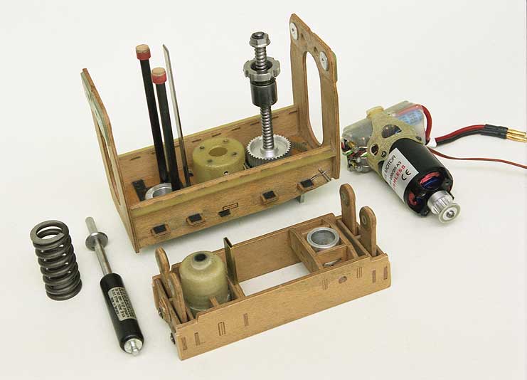
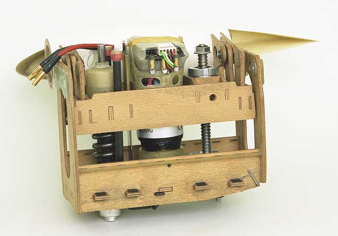
Single components of the driving mechanism
In front, one can see the swing
(frame of plywood) usually used in
EV-models for load balancing to the wing adapter
rollers. Behind this, there's the chassis of the mechanism first conceived
for the EV8.
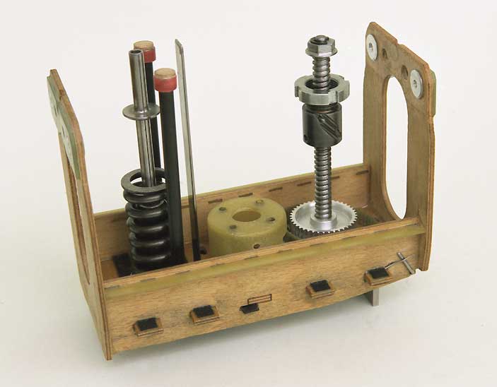
This is the chassis
with screw drive, springs and guide bar, but without the motor. It made the
installation of the drive as a whole in the fuselage and its removal possible.
The gas spring is also used as guidance for the steel spring.
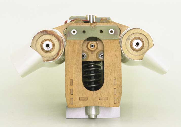
Front view

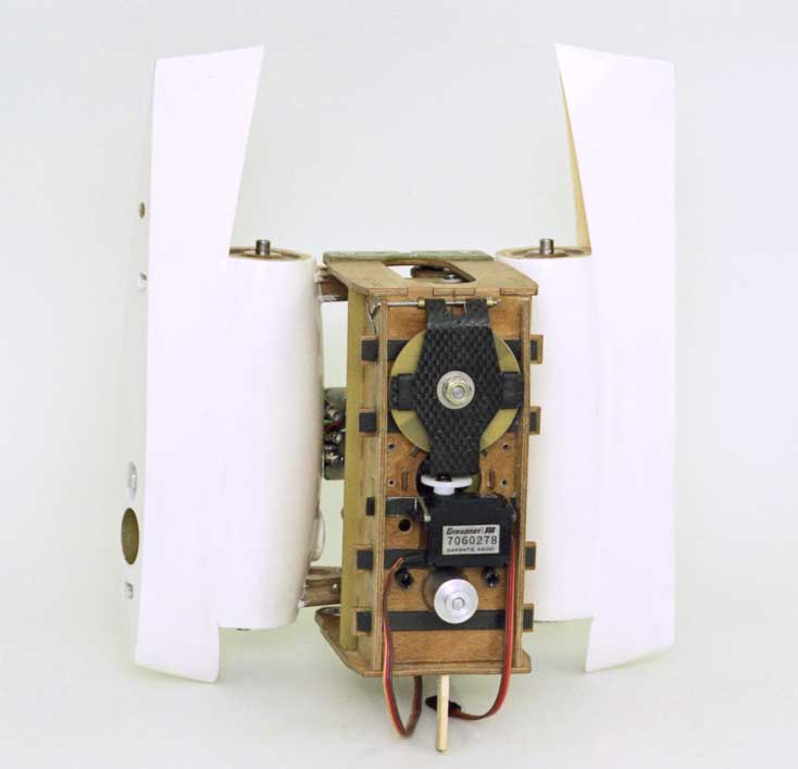
Back view

Bottom view
The mechanism of the brake as shown above has already been changed during
the tests of gliding flight. The braking forces have been too small for high
starts. The braking forces have been too small for high starts.
At the same time the connected digital rotation counter has been replaced by an analog position encoder (potentiometer).
Complete driving mechanism
The drive unit can be mounted relatively simply in and out of the fuselage
as a complete unit, weight 440 g [15 oz] (without wing adapter rollers). The
whole electrical equipment is placed in the front part of the fuselage.
Design
The whole design of the EV8 was made with CAD.
Thereby, a very compact construction could be obtained with passable effort.
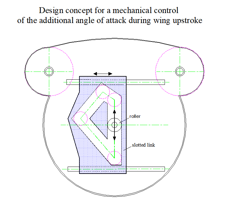
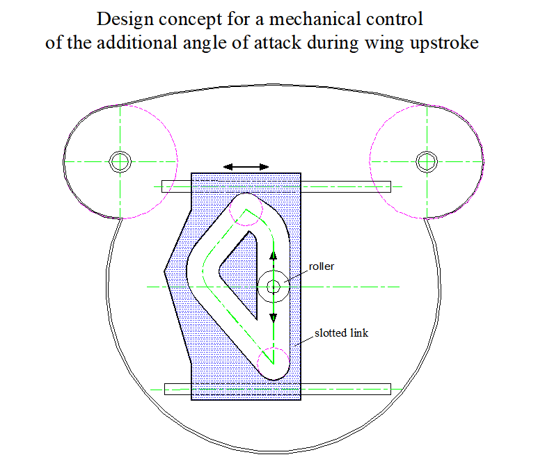
Control of the angle of attack during wing upstroke
Design concept for a mechanical control of the additional angle of attack
during wing upstroke (image of the guideway
with rounded corners, due to the mass inertia). The shape of the guideway
corresponds approximately to the course of the angle of attack α in the
article Lift during
wing upstroke, versie 10.1, Fig. 21, PDF 1.0 MB.
Towards the end of the downstroke, the lift decreases in the area of the wing tip. If the angle of attack increases near the wing root at the same time, so the arm wing takes over the lift from the hand wing in this way. This in birds enables a fast, self-acting reversal of the stroke motion of the arm wing and a matching, passive bending of the hand wing. So, in the lower stroke end position, the increase in angle of attack near the wing root is required for a well-functioning shift of lift. This important function is neglected in the calculation.
- The unit, consisting of the drive unit and the wing centre section (DW), is pivoted in the fuselage near the trailing edge of the wing, in such a way, that it can be turned upward for an additional angle of attack of the wing root (e.g. + 6 deg.).
- The roller moves up and down by the drive of the flapping wing.
- The lateral motion of the slotted link is used to control the additional angle of attack during wing upstroke. It must be converted into an up and down motion of the DW near the leading edge of the wing, either by a lever, a Bowden cable, or by a string.
- The lateral motion of the slotted link must be easy to move and cant-free in a guide which is fixed to the drive frame.
- In the area of the stroke end positions, the lateral motion of the slotted
link must be supported. When circulating the roller counterclockwise,
- near the upper final roller position to the left,
e.g. by a further slotted link with diagonally arranged guideway and a spring or by an angle lever-spring construction. - near the lower final roller position to the right,
e. g. by use of the second slotted link mentioned above with diagonally arranged guideway and a spring.
- near the upper final roller position to the left,
- The DW should be pulled by a spring to the zero position of the angle of attack (against the lift force).
It can also be used to control other angles of attack directly on the wing from the drive.
The upstroke of the arm wing in a distance flight consists of a relatively fast
upstroke motion, followed by a short waiting time at standstill in the upper stroke
end position The ball screw drive is well suitable for this task.
3. Functional description of the drive
When using a ball screw drive the direction of the motor rotation must change with every reversal of the wing flap direction. At first, it seems to be a little unfavourable. But if the reversal of rotation is largely affected by mechanical forces from the outside, losses of the motor are kept within limits.
The advantage of this drive technology lies in a relatively high degree of efficiency in the center part of the stroke.
Also at the previous EV-mechanism the drive motor was not very effective in the range of the final stroke position (no-load operation).
3.1 Functional diagram
-
- Functional diagram
At the EV8, the reversal of motion of the rotating drive- and wing masses is mainly affected by mechanical and aerodynamically forces:
- in the lower final wing stroke position by the lift forces of the wing and
- in the upper final wing stroke position by the so-called
end position spring
While reversing, the electromechanical forces should support the reversal of motion only a little
3.2 Reversal of the stroke movement
3.2.1 Reversal in the lower final wing position
-
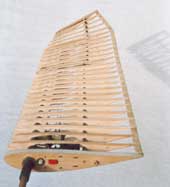
- Wing structure in upstroke twisting position
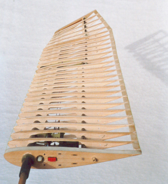
As with the EV6 and EV7, the flapping wing spar construction is designed in a way that its internal load always attempts to take the upstroke twist position. For illustrating the internal initial load the wing framework is arranged in cantilever supine position in the marginal photo. This initial load is important for the reversal of the motion in the lower final stroke position. The reversal happens approximately like this: (Numbering, Please look at the functional diagram)
-
The change-over of the motor happens when the wings reach their lower pre-final position during the downstroke. At first, due to the delay of time the speed controller works like a switch-off.
The lift at the wing is directed towards the still running downstroke. Thereby, the moved masses become slower. The lift force and the wing twisting become decreased, too.
-
If the downstroke comes to standstill in the lower final position, theoretically the wing twist equals the one in gliding flight. Also the lift force. Now it accelerates the wing upwards again.
Approximately at the same time the electrical run-up of the motor in the new rotation direction is getting started. But it still works without loading to a large extent. Via the ball screw drive the acceleration of the motor is mainly affected by the wing forces.
-
With increasing upstroke speed the lift forces continue to decrease. More and more the wing takes on the maximum upstroke twisting position. It is reached approximately in the lower pre-final position.
There, the motor has reached the full rotation speed. With its electromechanical force it now takes over the drive for the next upstroke of the wing and the tensioning of the compensating spring.
For the whole procedure the high efficiency of the ball screw drive is very important when converting a linear motion into a rotating motion.
The reversal of motion work - also of the rotating drive components - is primarily affected by the wing lift force.
Among the rotating drive components are the ball screw drive, timing belt pulleys and the motor (rotor). Because of its high rotation speed the angular momentum of the motor is considerable.
Also, you can support the reversal motion of the wing in the lower final position
by an end position spring
as at the (rack and
pinion drive system). This would be without importance for generating thrust,
but unfavourable for the lift.
3.2.2 Reversal in the upper final wing position
-
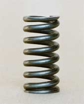
- End position steel pressure spring
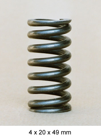
Instead of the wing lift a so-called end position
spring
made of steel takes over the positive and negative acceleration
of the masses in this range. Else, the motion sequence works analogically to aforesaid.
In the area of the upper final wing position there even during the upstroke decreasing lift always works against the reversal of motion. Hence, the end position spring also must overcome this force. Accordingly strong is its dimension (spring force max. 976 N).
If the energy recirculation of the wing mass momentum via the ball screw drive and the speed control in the accumulator are effective, the end position spring can later be designed frailer.
The flow of energy of the oscillating flapping wing mass is specified in the handbook, chapter 5.3.
4. Test rig
-
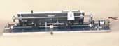
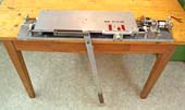
- Test rig for the
EV8 flapping wing drive

To test the drive functions of interacting electronics and mechanism there was built a test rig.
The pendulum hanging downwards has the same mass moment of inertia as the two flapping wing halves. The aerodynamically forces of up- and downstroke are roughly reproduced by adjustable dashpots.
But some questions remain open till the practical testing of power flight.
5. Related Links
- Product data sheet
Ball Reverser Actuator
by the company Norco Inc. (USA): http://www.motiontech.com.au/assets/pdf/Flennor Norco Ball Reverser Actuator 230712.pdf (0,2MB) - Lightweight, resilient high-performance power unit with high efficiency for
the elastic motion of a robot arm.
A New Prismatic Series Elastic Actuator with Compact Size and High Performance
by Nicholas Paine and Luis Sentis from The University of Texas at Austin, USA, 2012:
Video: https://www.youtube.com/watch?v=KaQ6lx3ifPU
Journal Publication:
http://www.me.utexas.edu/~lsentis/files/Prismatic-SEA-paine.pdf (3.8MB)