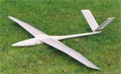
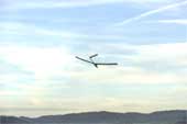
Ornithopter model EV8
Content:
1. Manufacturing of the fuselage
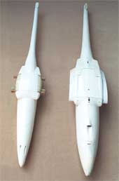
Constructing male mould of the fuselage
For a precise mechanism- and wing connection the position and direction
of the main frames and the wing stroke axis needs to be determined right
from the beginning.
To the right and left side of the shoulder component the turned
halves of the profile spindle for the wing root transition are
adjusted.
Finish male mould of the fuselage
with female moulds of the fuselage cover. As a tail boom
a conical tube will later be inserted in the rear
of the finished fuselage.
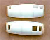
Female mould of the fuselage
The female mould and the fuselage are manufactured in the usual
glass fibre (GRP) construction.
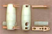
Reinforcement of the fuselage
Without the wing adapter rollers the deep cut in the fuselage
contour is good to be seen in the side view of the fuselage.
For reinforcing this part a strong carbon fibre tube together
with the main frames will be inserted into the left and right
side of the fuselage. At back and front these tubes taper off very slender at the sides of
the fuselage. Hence the fuselage gets very warp resistant.
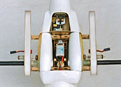
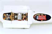
Here the center piece is ready to hold the chassis with the driving
mechanism.
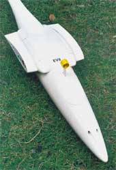
Finished fuselage
- length
- max diameter
- weight without mobile equip
- 1,47 m
- 125 mm
- 600 g
- [58 in]
- [4.9 in]
- [21 oz]
Comparison of dimension
Due to its smaller drive mechanism the EV8 could
be constructed with a relatively slim fuselage. This results in positive
effects on its total weight and its handling.
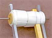
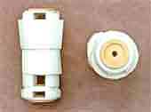
1.1 Wing adapter rollers
The manufacturing begins with the end plates of plywood and the layering of the rigid foam sections according to the later gaps. For their accurate alignment rectangle profiles are used.
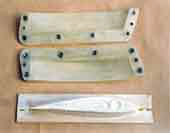
1.2 Wing root fairing
For the transition from the symmetrical profile of the wing adapter roller to the cambered wing airfoil a mould construction is necessary, too.
Fuselage-wing transition
Sloping of the stroke plane by 6 degrees - from top-back to
down-front - results in a straight trailing edge on the fuselage-wing
transition (please look at the handbook,
chapter 8.8).
2. Control of flight speed
A flying model - especially an ornithopter in power flight - is flying optimally only in a relatively small speed range. In gliding flight the elevator unit normally works as an automatic speed controller. Nevertheless in practice it comes to great speed fluctuations by radio-control commands and in powered flight (please look at Flight stability of ornithopters at the EV7).
With the EV8 an electric controller should ensure the keeping of the optimal power flight speed. This prevents, in particular, a stall as a result of too low flight speed, especially when climbing in powered flight. With a speed controller the slope angle will only be influenced by thrust resp. by the stroke speed. More or less thrust results in more or less climbing. A remote control of the elevator is then no longer required in the powered flight.
Controller
A controller of flight speed for helicopters for combustive motors is used.
Its properties to control have proofed quite useful in the control loop designed
here.
Airspeed sensor
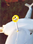
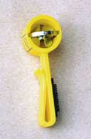
The vane sensor of a paragliders airspeed sensor works as a speedometer.
It is designed for a wireless rotation speed transmission (type Skywatch,
Swiss made). A small magnet rotates with the vane.
The rotation of the magnet is scanned by the rpm sensor of the helicopter-speed controller, which otherwise detects the rotation speed of the rotor blades.
The desired rotation speed (resp. the nominal flight speed) can be predetermined by radio-control, and its influence can be activated and deactivated. For testing, the van sensor can be brought to the desired rotation speed with a magnet which is mounted at the end of the motor shaft.
Phygoide
The slow oscillation of the airspeed almost occurring in every gliding
flight (re Phygoide
, please look at related link 1)
can be avoided with the electric regulation. The model flies its angle
of glide as controlled by rails. Also miscarried hand launches with
unfavourable angles of glide in the beginning are no problem anymore.
The model directly passes into the angle of glide given by the desired speed.
However, landing should better be tried with switched off controller.
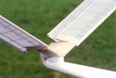
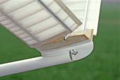
2.1 Becker rudder
For improving the elevator effect a linkage according to the principle of a Becker rudder was applied to the EV8. Otherwise such a thing is used particularly on ships. It increases their capability of manoeuvre.
With the Becker rudder control surface and deflection flap are moved synchronously with only one lever. The elevator changes its angle of attack and camber in the same tenor. In this way, the effect of the elevator is bigger as with only one of the two modifications.
Normally small rudder throws are sufficient with an activated controller of flight speed. The advantage of the Becker rudder is mainly obvious when the controller is switched off.
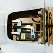
Mechanical mixer for the V-tail
Here, instead of the gas servo of the helicopter engine the controller
steers the elevator servo. A mechanical mixer had to be added to the V-tail linkage
already existing in the
EV8.
A T-tail would have been better.
3. Articulated flapping wings
In connection with the EV-Models there have been
developed a number of further flapping wing designs from which arose the aeroelastic
controlled articulated flapping wing
of
the EV8.
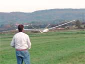
First experiments with gliding flight
were succeeded. Also high starts have been made.
The gliding flight experiments with the EV8 have been closed successfully in 2003. The first attempt of a power flight did not result in wing flapping due to a handling error - but in an unfortunate landing. A wing spare got broken.
4. Related links
- Simulation of the phygoide by Peter Rother:
http://www.aerodesign.de/peter/1998/phygosim.htm


