Cardan gear mechanism
of the ornithopter models EV1 to EV6
Content:
- 1. Cardan crank mechanism in general
- 2. Transition between gliding
and powered flight
by reversion of rotation in EV1 to EV4 - 3. Transition between gliding
and powered flight
by a step switching system with a servo
in EV5 and EV6 - 4. Direct adjustment of the
flapping angle with an servo drive - 5. Related Links
Note:
- Adobe Flash Player would be required to operate the cranks shown below. However, this should no longer be used. Therefore, when clicking on a crank image, only an animation is loaded (to operate the Cardan gear mechanism without Flash Player, please see related link 1).
1. Cardan crank mechanism in general
A cardan crank mechanism is a way of converting rotary motion into straight line motion. It was invented in the 16th century by the Italian mathematician Girolamo Cardano.
A cardan gear mechanism with a crank pin especially consists of an internal gear and a planetary gear with a crank pin. The internal gear has a diameter exactly twice the size as the planetary gear. Every crank pin on the planetary gear pitch diameter moves on a straight line of an internal gear diameter.
-
Only the main wheel in the center of the unit is driven by the coreless motor. The axle of the planetary gear is connected to this wheel.
-
To generate the flap moving of the wing only one crank pin is needed.
-
To actively control the twisting or pitching of a flapping wing two staggered crank pins are needed. The main crank pin generates the flapping and the phase displaced movement of the control crank pin the twisting or pitching of the wing.
-
Here, in power flight the control crank pin always runs ahead of the main crank pin - like the leading edge of the wing compared to the main spare while flapping.
-
The vertical movement of both crank pins are transmitted by scotch yokes to the flapping wing (linkages please see the driving mechanism of the EV4).
-
In the gliding flight position both scotch yokes are in their stroke center and according to this also the flapping angle and the angle of setting of the wing.
-
When the drive unit in the gliding flight position is stopped in a crank dead point it is able to take any wing forces in vertical direction. Therefore a brake is not necessary.
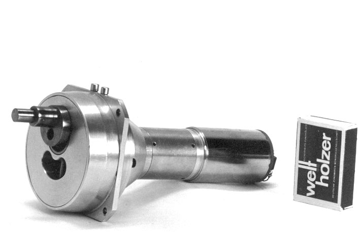
Cardan crank
manufactured for the EV1. This special planetary
gear mechanism converts the rotary motion of the electric motor (rated input
power 85 Watt) into a straight line reciprocating motion of the crank
pin. A scotch yoke was only used to switch between gliding and powered flight.
- Glide is obtained by orienting the path line of the main crank pin horizontally.
- Powered flight is obtained by orienting the path line of the main crank pin vertically.
On top of the gear case there are to see two triggers for two different settings of glide positions. The motor has stopped in the dead center of the crank. In this way the glide position was locked.

The 2 mm stagger between the main and the control crank pin is visible in the photography.

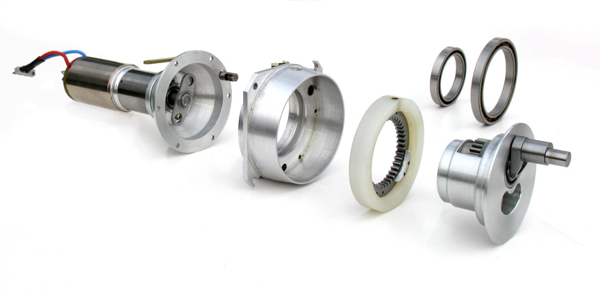
Drawing of complete crank drive unit
For further details and technical data, please see:
- Plans of the single components (PDF 1.4MB) with 18 pencil drawings, in German
- Report about The development of the EV- flapping wing models (PDF 1.4MB) in German
- my patent DE 26 28 846 (application 1976 related link 2)
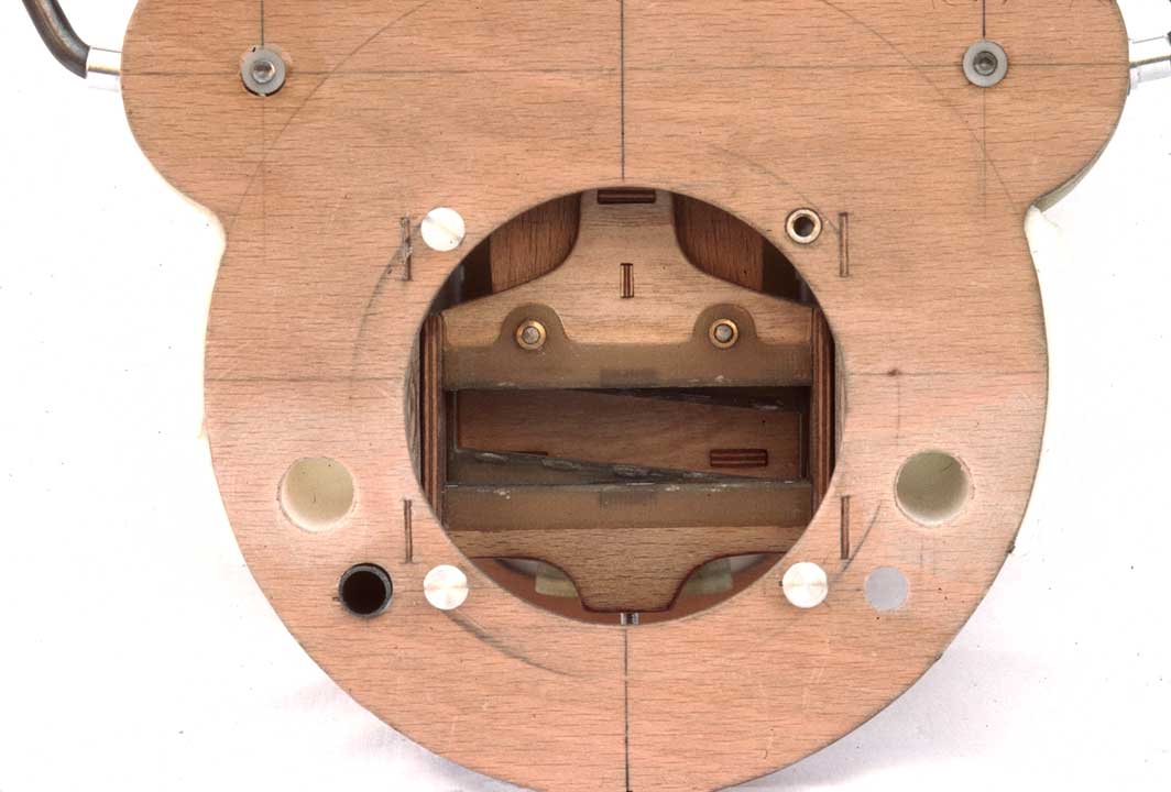
Scotch yokes
in the driving mechanism of the EV4.
The horizontal slotted main scotch yoke (with slide of steel) is good to see.
The inclined slide of the control scotch yoke behind is still recognizable.
2. Transition between gliding and powered flight by reversion of rotation in EV1 to EV4
With each reversal of the rotation the internal gear gets rotated by 90 degrees between two corresponding blocks. It can move freely between the stops.
Prerequisite for the switching and keeping of the power flight position of the internal gear is a continuous braking force on the main crank pin or on the scotch yoke.
For funktion, please see note above
(Animation 1.1 MB, in German)

The path line of the smaller control crank pin (control crank pin lilac, main crank pin blue) being slanted in gliding flight is good to be seen by its scotch yoke.
3. Transition between gliding and powered flight by a step switching system with a servo in EV5 and EV6
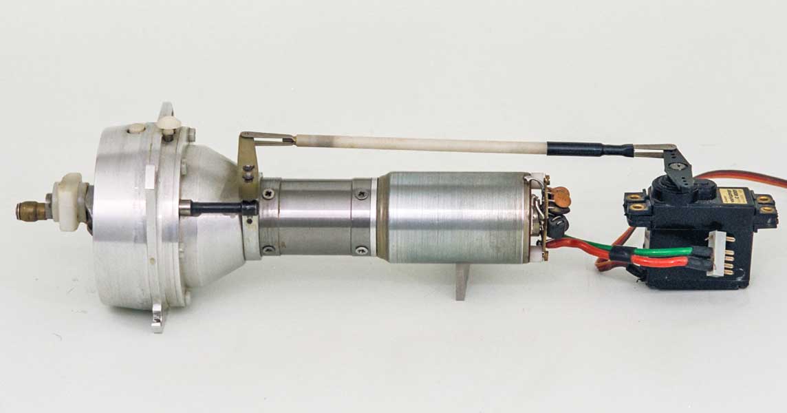
Altered cardan gear mechanism
Switching between gliding and power flight at EV5
and EV6 was no longer affected by reversing the
direction of rotation, but by a servo controlled step switching system of
the internal gear of the cardan gear mechanism. The locking bolt of the internal
gear was actuated by a simple remote controled servo. Also this variation
is enclosed in the Plans
of the single components (PDF 1.4MB) with 18 pencil
drawings, in German.
Only while switching between gliding and power flight a continuous braking force is needed on the main crank pin or on the scotch yoke. Subsequently the setting of the internal gear will be locked.
For funktion, please see note above
(Animation 1.9 MB, in German)
4. Direct adjusting of the
flapping angle with an servo drive
In addition to the main drive with only one rotation direction an servo drive with a reversing rotation direction is needed.
The performance of the servo drive depends on the occurring crank forces and the desired speed control. Designed for short term use is sufficient.
For funktion, please see note above
(Animation 4.2 MB, in German)

The flapping angle of the wings can be adjusted stageless.
For the single steps the path line of the main crank pin is represented as a white dotted line.
In this case an internal-combustion engine was designed as the main drive and an electric motor as the servo drive. This drive concept for ornithopters is very reliable, because the transition to gliding flight can also be used in case of a failure of the main drive.
Such a drive unit with changeable stroke has not been built yet.
5. Related Links
- To operate the Cardan gear mechanism
The Wayback Machine, Internet Archive, 2019
https://web.archive.org/web/20190725161140/http://www.ornithopter.de/english/crank.htm (please wait a moment) - Here you can find informations about my patent specification of the cardan
gear mechanism with reversal of rotation direction (like chapter
2.)
https://depatisnet.dpma.de/DepatisNet/depatisnet?action=pdf&docid=DE000002628846C2
Both other variants of the crank I have not applied for a patent. - Cornell University, Kinematic Models for Design, Hypocycloid Straight-line
Mechanism:
http://kmoddl.library.cornell.edu/model.php?m=137